Serial Tap
Note
This page is for the Serial Tap Tap board. For the plugin, see the plugin docs.
Serial Tap is an affordable serial sniffer that can monitor RS232, RS48, and TTL-level UART communications. The Tap connects to your PC via a USB cable and is compatible with IO Ninja terminal/sniffer software.
Features
Serial Tap is designed for use with IO Ninja software (http://ioninja.com/).
Monitors
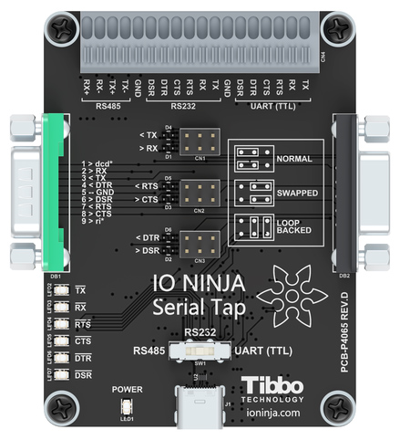
TX,RX,RTS,CTS,DTR, andDSRlines [1] of serial ports.All inputs are connected to an 18-position, quick-release terminal block.
Has three modes:
RS232,RS485[2], andUART(TTL[3]), selectable via a switch:RS232mode:Two onboard
DB9connectors — male and female — offer true “cable wedge” sniffing [4].Six jumpers for swapping and loopbacking signals within
RX/TX,RTS/CTS, andDTR/DSRpairs [5].Six bi-color LEDs indicate the status of monitored lines and allow distinguishing between the positive voltage (red), negative voltage (green), and zero voltage (off) states [5].
DB9connectors additionally pass throughDCDandRIsignals (without monitoring them).
RS485mode allows to monitorTXandRXsignal pairs.UART(TTL) mode allows to monitor UARTs of IC chips with logic levels from 3.3V to 5V.
Full-speed (12Mbps) USB2.0 interface on a USB-C connector.
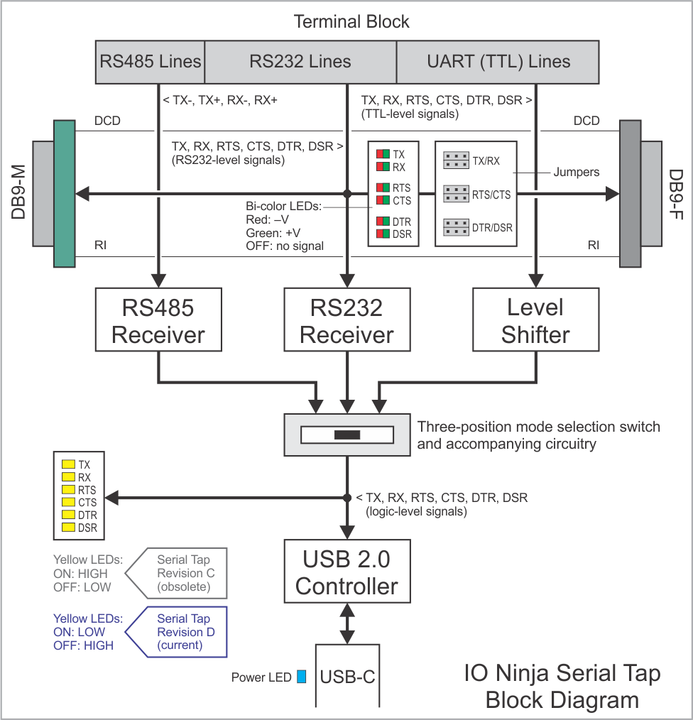
Six yellow LEDs indicate the state of six monitored lines as they enter the USB controller. LEDs turn on when the lines go LOW [6].
USB-powered, no additional external power necessary.
Supplied with a USB-C cable and two
DB9gender changers.Compact, outside dimensions only 82 x 74 x 30 mm.
Block Diagram
Wiring Diagrams
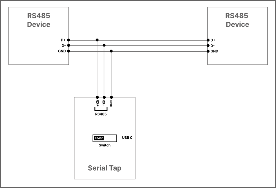
RS485
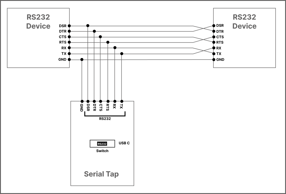
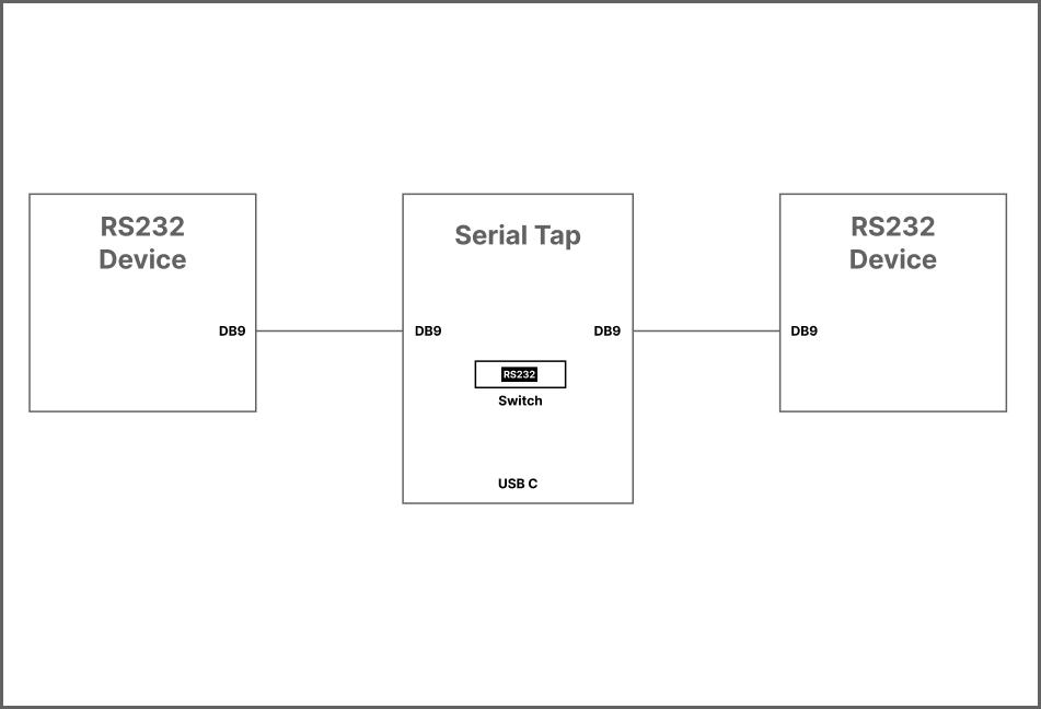
RS232 (terminal block)
RS232 (DB9)
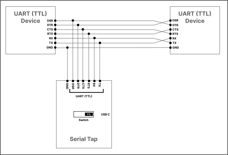
UART (TTL)
Wedge RS232 Monitoring
The Serial Tap allows you to insert (wedge) it in between two RS232 devices. Here is how this is done.
Let’s suppose that two serial devices are interconnected by a serial cable. Let’s also suppose that the first device has a DB9-F connector, while the second device has a DB9-M connector. The serial cable is, therefore, of the M-to-F type.
To wedge the Serial Tap between these two devices, you will need the second M-to-F cable:
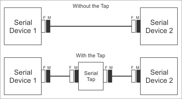
Of course, DB9 genders on the serial devices may differ from the above example, and so your serial arrangement may be different. To aid you in the “wedging process,” each Serial Tap comes with two DB9 gender changers.
Jumper Pairs
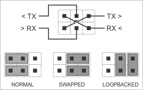
The Serial Tap has an additional useful feature allowing you to swap and loopback the signals in TX/RX, RTS/CTS, and DTR/DSR signal pairs. To achieve this, two jumpers are provided for each of the three pairs. There are three standard jumper configurations:
Normal — In this position, the lines are arranged in such a way that wedging the Tap between the serial devices does not change anything. Meaning,
TXon one end goes toRXon another end, and vice versa.Swapped — This swaps signals in a pair. Meaning,
TXgoes toTX, andRXgoes toRX.Loopbacked — Both serial devices “receive back” their own signals. Meaning, the
TXline on each side “comes back” through theRXline.
The following diagram illustrates the jumper arrangements. The diagram shows the jumpers for the TX and RX signal pair. RTS/CTS and DTR/DSR jumpers work in the same way.
Common Mistakes
When setting up Serial Tap for RS485 communication, it’s crucial to avoid common wiring mistakes that can lead to malfunction or ineffective monitoring.
Miswiring Differential Pairs
A frequent error involves connecting the D+ and D− lines from one device to the TX+ and TX− inputs of Serial Tap, and the D+ and D− lines from another device to the RX+ and RX− inputs. This configuration assumes that Serial Tap will forward data between these lines, which it does not. Serial Tap is designed solely for passive monitoring and does not facilitate data forwarding between connected devices.
To correctly monitor RS485 communication, connect the D+ and D− lines from the RS485 bus directly to the corresponding monitoring inputs on Serial Tap. Ensure that the connections are made in parallel with the communication lines, allowing Serial Tap to observe the data without interfering with the bus operation.
Inappropriate Use of DB9 Connectors
Another common misuse is attempting to connect RS485 devices equipped with DB9 connectors, such as FTDI RS485 adapters, directly into Serial Tap’s DB9 ports. Serial Tap’s DB9 connectors are not designed to interface directly with RS485 devices in this manner. Doing so can result in improper operation or even damage to the equipment.
Instead, use appropriate breakout cables or adapters that match the pinout and electrical characteristics required for safe and effective monitoring. Always refer to the Serial Tap documentation and the RS485 device specifications to ensure compatibility and correct wiring practices.
Using the Serial Tap
Please see the documentation for the Serial Tap plugin.
Specifications
The Serial Tap is supplied with a USB cable and two DB9 gender changers.
Hardware Specifications [7] [8]
Parameter |
Specification |
|---|---|
USB port |
USB 2.0, full-speed (12 MHz), USB-C connector |
Maximum baudrate |
2,764,800 bps |
Operating temperature |
0 to +60 degrees C |
Operating relative humidity |
10–90% |
Mechanical dimensions |
82 x 74 x 30 mm |