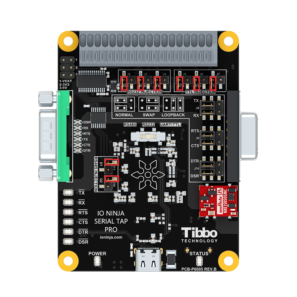
Serial Tap Pro
Serial Tap Pro is a high-performance hardware sniffer for RS232, RS485, and TTL-level UART communications, designed to meet the demands of advanced serial diagnostics. Serial Tap Pro taps into both data and control lines and streams captured traffic to IO Ninja software in real time. In addition to all the great features of the original Serial Tap, such as RS232 line jumpers, convenient quick-release terminal block, and DB9 wedge-monitoring, the Serial Tap Pro supports 2Mbps+ baud rates, features electrically isolated serial interfaces, and allows users not only to monitor but also to drive serial lines (injection). It supports 9-bit data, and delivers microsecond-precision hardware timestamps for each byte, ensuring accurate timing analysis. Featuring guaranteed byte-perfect sequencing, the Serial Tap Pro is the ultimate tool for engineers, developers and QA testers who require reliable, high-fidelity serial communication analysis on Windows, MacOS or Linux.
Board
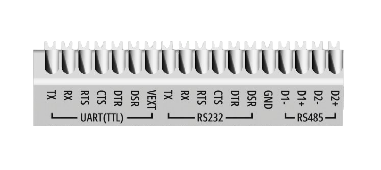
Terminal Block
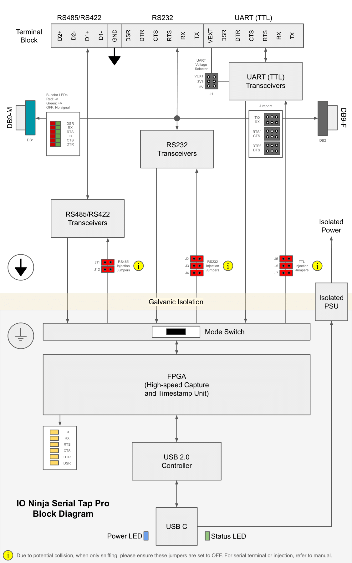
Block Diagram
Wiring Diagrams
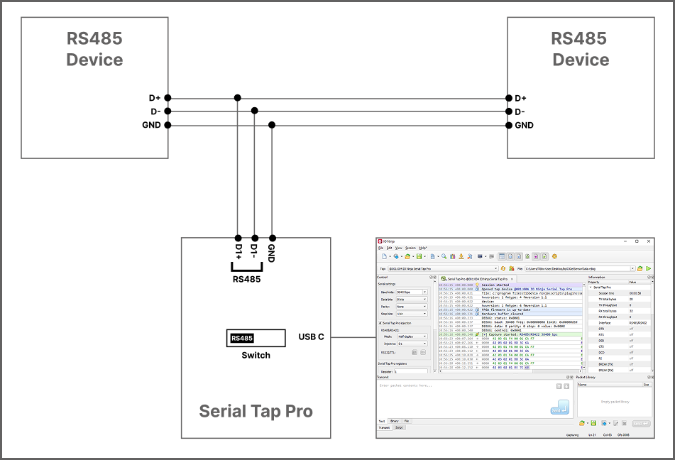
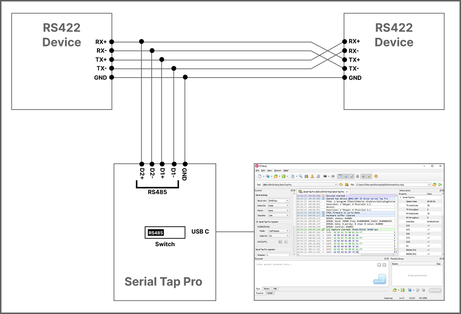
RS485
RS422
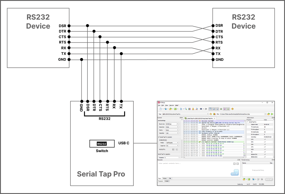
RS232 (terminal block)
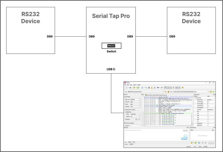
RS232 (DB9)
Note
Jumpers are available for scenarios where non-criss-crossing DB9 cables are being used. See RS232 DB9 Jumper Pairs for more information on how to use Serial Tap Pro’s DB9 jumper pairs.
Warning
A common misuse is attempting to connect RS485 devices equipped with DB9 connectors directly into Serial Tap Pro’s DB9 ports. Serial Tap Pro’s DB9 connectors are not designed to interface directly with RS485 devices. Doing so can result in improper operation or even damage to the equipment. Instead, use appropriate breakout cables or adapters that match the pinout and electrical characteristics required for safe and effective monitoring.
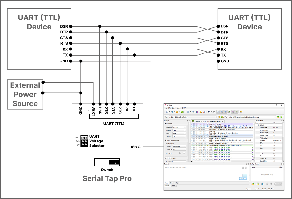
UART (TTL) VEXT (default)
UART (TTL) 3V3
UART (TTL) 5V

Note
VEXT is the default UART (TTL) voltage position at the time of shipment, but it requires an external voltage line to be connected to the terminal block. If you are not using external voltage line, then you must change the J1 jumper to an appropriate position (either 3V3 or 5V).
Injection Jumpers
Serial Tap Pro allows injection of data directly into serial lines. However, in order for you to be able to inject via the Serial Tap Pro plugin, as demonstrated here, you will first need to put the relevant jumper for the serial line you wish to inject into to an ON position. By default, all jumpers are OFF.
The tap features 8 injection jumpers, 1 for each serial line. Each injection jumper has a red jumper cap. To enable injection for that line, orient the cap so that it sits on both pins (ON). For example, if you wanted to inject into the tap’s D1 line, you would set the D1 jumper (J11) to the ON position.
Injection Jumpers
Jumper |
Interface |
Injection Line |
|---|---|---|
J2 |
|
|
J3 |
|
|
J4 |
|
|
J5 |
|
|
J6 |
|
|
J7 |
|
|
J11 |
|
|
J12 |
|
|
Warning
Due to potential collision, when only sniffing, please ensure injection jumpers are set to OFF.
Warning
When injecting to RS232, please ensure that jumper pairs are not set to “LOOPBACK”, the right DB9 connector is not connected, and that the TX/RTS/DTR lines are not being driven by a connected USB-to-RS232 adapter on the terminal block.
The same precaution applies to TTL injection; when injection jumpers are ON, make sure the connected USB-to-TTL adapter does not drive the TX/RTS/DTR lines.
When injection jumpers are enabled, the FPGA actively drives the TX, RTS, and DTR lines. If an external USB-to-Serial adapter simultaneously attempts to drive these same lines, bus contention and unpredictable behavior may result.
Note
When using RS485/RS422 injection with the injection jumper OFF, IO Ninja will still log outbound packets as if they were transmitted. However, in this mode, the data is not actually sent on the physical bus. This differs from RS232 and TTL interfaces, where injection is gated by jumper state and transmission is inhibited when the jumper is OFF.
This behavior is by design and reflects a fundamental characteristic of RS485 buses: they are half-duplex by nature. Unlike RS232 or TTL, RS485 does not allow simultaneous transmission and reception on the same pair of lines. Consequently, the Serial Tap Pro cannot verify whether a packet was physically transmitted when the injection jumper is OFF. For consistency and clarity, IO Ninja always logs attempted transmissions on RS485 interfaces, regardless of jumper configuration. This is not a bug or limitation, rather, it is an inherent aspect of how RS485 injection is implemented in hardware.
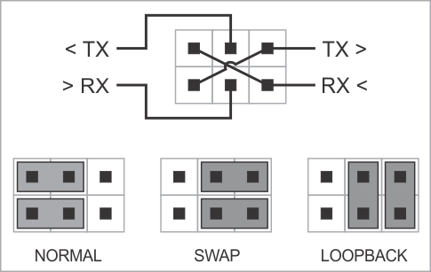
RS232 DB9 Jumper Pairs
Serial Tap Pro has an additional useful feature allowing you to swap and loopback the signals in TX/RX, RTS/CTS, and DTR/DSR signal pairs. To achieve this, two jumpers are provided for each of the three pairs. There are three standard jumper configurations:
NORMAL — In this position, the lines are arranged in such a way that wedging the Tap between the serial devices does not change anything. Meaning,
TXon one end goes toRXon another end, and vice versa. This mode will work for most scenarios.SWAP — This swaps signals in a pair. Meaning,
TXgoes toTX, andRXgoes toRX. Sometimes DB9 cables don’t do criss-crossing, so criss-crossing can be achieved this way instead.LOOPBACK — Both serial devices “receive back” their own signals. Meaning, the
TXline on each side “comes back” through theRXline.
The following diagram illustrates the jumper arrangements. The diagram shows the jumpers for the TX and RX signal pair. RTS/CTS and DTR/DSR jumpers work in the same way.
Warning
When injecting to RS232, please ensure that jumper pairs are not set to “LOOPBACK”.
RS485 Data Direction Detection
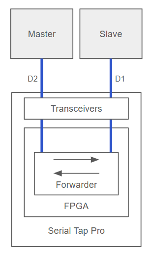
Serial Tap Pro features RS485 data direction detection, enabling you to precisely identify which device on a RS485 bus is transmitting at any given moment. In typical half-duplex RS485 configurations, all nodes share a single differential pair, which makes determining the origin of a message difficult. Serial Tap Pro addresses this by inserting itself in-line between two physical points on the RS485 bus. It connects to the differential pairs D1+/D1− and D2+/D2−. Acting as a transparent man-in-the-middle, its FPGA core actively forwards data between these two bus segments. This approach ensures that for every byte received, the FPGA knows whether it came from the D1 or D2 side, allowing it to infer the sender’s direction without relying on protocol decoding or timing heuristics. Thanks to this method, RS485 data direction detection works at the physical layer, independent of the protocol being used in the session. An example is shown below:
Using Serial Tap Pro
Basic Setup
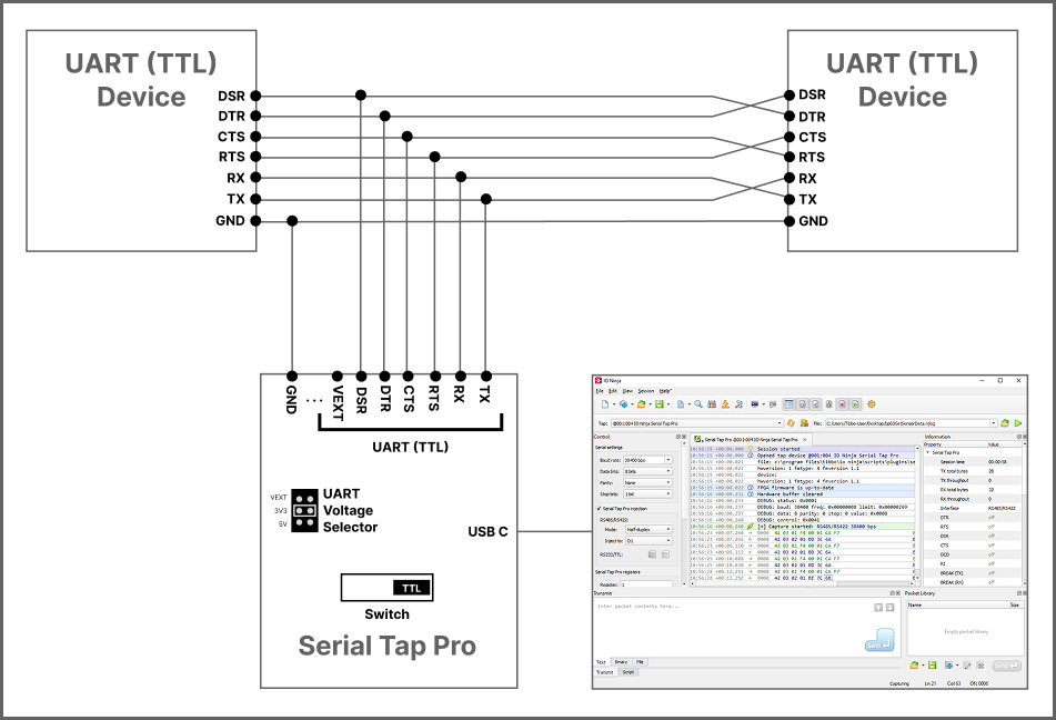
Ensure your Serial Tap Pro is connected to your serial device and your computer.
Note
Please see the Wiring Diagrams section for guidance on connecting your tap.
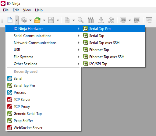
In IO Ninja, click the “New Session” dropdown and select a new “Serial Tap Pro” session.
If not selected automatically, select your Serial Tap Pro from the “Tap:” dropdown.

Note
If you can’t see your tap, press the “Refresh” button.
Adjust settings as needed via the “Settings” button (see “Settings” section below for details).
Note
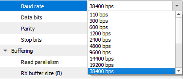
Before capturing, you should select the proper baud rate (and other serial parameters). If you need to set a non-standard baud rate, you can type it in directly to the “Baud rate” input field.
Start capturing by clicking the “Capture” button located to the right of the “Tap:” dropdown.

Note
If you encounter permission denied errors on Linux, please see this knowledge base article.
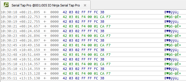
Monitor traffic in the “Serial Tap Pro” tab.
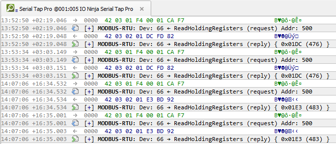
If you wish, add a layer such as Modbus Analyzer for easier analysis.
Automatic Baud Rate Detection (ABR)
Starting with IO Ninja version 5.9.0, Serial Tap Pro features automatic baud rate detection (ABR). Unlike most ABR-enabled tools, this detector doesn’t rely on specific byte patterns. In most cases, just a few random bytes captured on the wire are enough for it to determine the serial parameters, which then appear in the Information Pane.
You can adjust the tap settings accordingly, or continue monitoring – the detector is non-intrusive, offering a hint rather than automatically changing serial configuration (which could otherwise cause unintended side effects).
What’s more, Serial Tap Pro ABR works even when devices on a serial link operate at different baud rates – a common cause of serial communication errors. With Serial Tap Pro, such mismatches become immediately evident, saving you considerable debugging time.
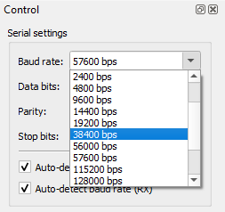
In the “Control” pane, enable automatic baud rate detection on one or both data lines (TX, RX).

Optionally, fine-tune advanced ABR settings in the “Settings” dialog.

Standard baud rates only: When enabled, this setting restricts the baud-rate detector to scan and report only standard baud-rate values (9600, 19200, 38400, 115200, etc.). When disabled, the detector scans the whole baud rate detection range and reports non-standard baud rates as well.
Baud rate grid cell count: This value determines how many “cells” (or discrete divisions) the ABR algorithm uses for simulation across the detection range. Only available when “Standard baud rates only” is disabled.
Edge error tolerance (%): This setting indicates the allowable percentage deviation (tolerance) in the timing of signal edges (bit transitions) that the detector will accept as valid during its analysis. For example, if the tolerance is 10%, the detector will ignore edge timing deviations of up to ±10%.
Horizon (ms): This setting defines the maximum time frame in milliseconds over which the ABR algorithm will observe signal edges (bit transitions) to make its judgment on the baud rate. All serial events beyond this horizon are essentially ignored.
Observe the automatically detected baud rate and UART frame size in the “Information” pane.

Note
ABR depends on Serial Tap Pro timestamps, which have a resolution of 1 mcs. As such, ABR detection becomes less reliable at high baud rates (above ~300,000 bps), with 1 Mbps being a strict upper bound of the detection range.
This is generally not a significant limitation. ABR is primarily needed when working with legacy devices lacking datasheets and documentation – such devices typically operate at much lower baud rates.
Update the baud rate via the “Serial settings” section of the “Control” pane accordingly.
Warning
ABR is not “free” in terms of USB bandwidth. Once ABR has helped you determine the correct serial parameters, it’s best to disable it to minimize unnecessary USB load.
Flipping Line Directions
When tapping into bi-directional serial lines, it is not always obvious which direction the data is flowing, e.g., which side is transmitting (TX) and which is receiving (RX). Depending on how your tap wires are physically connected, the traffic may appear reversed in the log view. This can make it difficult to interpret which endpoint initiated a message and which replied. To address this, the Serial Tap Pro plugin includes a “Flip line directions” checkbox in the “Serial Tap Pro log” section of the “Control” pane. When this option is enabled, the plugin inverts the logical direction of the lines. What was previously displayed as TX will now appear as RX, and vice versa. The same flipping applies to control lines like DTR/DSR and RTS/CTS.
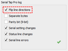
Note
Enabling the “Flip line directions” setting only affects the view of data inside IO Ninja, nothing on the Serial Tap Pro itself, or its redirect lines are physically changed.
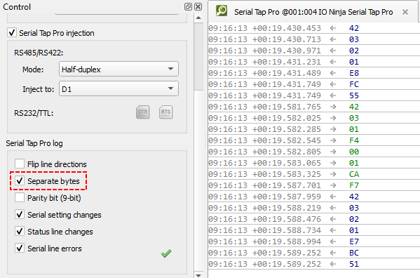
Separating Bytes
Serial Tap Pro captures microsecond-precision hardware timestamps for each byte, but to actually see these individual time stamps inside IO Ninja, you must enable “Separate bytes” via “Settings”, or through checking “Separate bytes” in the “Serial Tap Pro log” section of the “Control” pane.
Injecting Packets
Ensure the jumper for the serial interface/line you are using, e.g.
D1orD2isON.
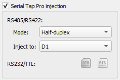
Ensure “Serial Tap Pro injection” in the “Control” pane is enabled.

In the “Serial Tap Pro injection” section, you are able to select the “Mode” and the line you wish to inject to for
RS485/RS422, and given the option to select fromDTRorRTSforRS232/TTL.
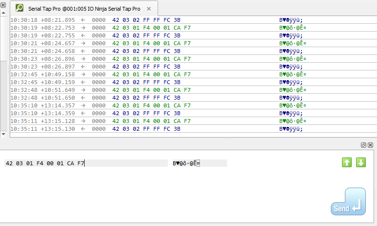
Note
In RS485/RS422 mode, Serial Tap Pro colors data from D1 blue and from D2 green. Since injected data shares the same line as captured data, it would normally appear in the same color, making it hard to distinguish. To fix this, the “Mode” dropdown in the Injection Panel controls how the FPGA emits notification codes for injected bytes, affecting their color in the log.
- Half-duplex and Half-duplex D1↔D2
In both modes, the FPGA inverts the notification codes for injected bytes — injected data on
D1appears green, and onD2, blue. This helps separate captured vs. injected traffic. The difference between these modes is that “Half-duplex D1↔D2” mode is used for direction detection via forwarding, where the FPGA actively relays data betweenD1andD2bus segments to infer message direction at the physical layer.
- Full duplex
In this mode, the FPGA does not invert notification codes, so everything captured on
D1is colored blue, and everything that is captured onD2is colored green.
Summary
Mode |
Line |
Captured Byte Color |
Injected Byte Color |
|---|---|---|---|
Half-duplex |
D1 |
Blue |
Green |
D2 |
Green |
Blue |
|
Half-duplex D1 ↔ D2 |
D1 |
Blue |
Green |
D2 |
Green |
Blue |
|
Full-duplex |
D1 |
Blue |
Blue |
D2 |
Green |
Green |
Using the “Transmit” pane, send serial packets just like you would with any serial terminal.
Displaying Parity Bit (9-bit)
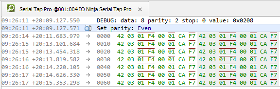
Serial Tap Pro supports 9-bit UART communication, a variant sometimes used in industrial and embedded systems for distinguishing between address and data frames. This feature is particularly valuable in multipoint serial networks, where the 9th bit serves as a hardware-level address indicator, allowing slave devices in legacy SCADA, industrial controllers, and other systems to efficiently skip all bus traffic not addressed to them— thus optimizing their power consumption. In IO Ninja, the 9th bit (parity bit) is clearly indicated with a red overline, making address bytes immediately recognizable during trace analysis.
In the “Serial settings” section of the “Control” pane, select a parity from the “Parity” dropdown.
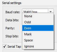
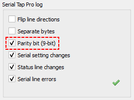
In the “Serial Tap Pro Log” section of the “Control” pane, enable “Parity bit (9-bit).”
Check the log to see the parity bit overlined in red.
Note
When parity is set to “Ignore”, the parity bit is enabled, but IO Ninja will not perform any kind of error checking based on parity.
Settings
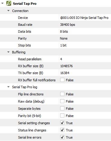
Setting |
Description |
Default |
|---|---|---|
Device |
The Serial Tap Pro that should be used. |
|
Notification delay (ms) |
The maximum delay until a USB bulk transfer is sent out. |
20 ms |
Baud rate |
The serial baud rate. |
38400 bps |
Data bits |
Serial data bit count (word size). See available options. |
8 bits |
Parity |
When enabled, the Serial Tap Pro plugin indicates the 9th parity bit using a red overline above the parity bit, making it easy to distinguish at a glance. See available options. |
None |
Stop bits |
Serial stop bit count. See available options. |
1 bit |
Auto-detect baud rate (TX) |
Enable auto-baud rate detector on the TX line. |
False |
Auto-detect baud rate (RX) |
Enable auto-baud rate detector on the RX line. |
False |
Standard baud rates only |
Limit the auto-baud rate detector (ABR) to standard baud rates only. |
True |
Baud rate grid cell count |
Number of cells in the ABR baud rate approximation grid. |
10000 |
Edge error tolerance (%) |
The auto-baud rate detector (ABR) ignores edge errors within this percentage tolerance. |
10 % |
Horizon (ms) |
Maximum event horizon for auto-baud rate detector. |
1000 ms |
Read parallelism
(Windows-only)
|
Maximum number of read requests to issue in parallel. Having more than one pending read at a time helps with increasing read throughput when incoming data arrives in rapid streams (after filling one user buffer, the kernel can immediately switch to the next one without any waiting). Increasing this number beyond 4 usually won’t yield any extra performance gains. |
4 |
RX buffer size (B) |
The full size of the incoming data ( |
16KB |
TX buffer size (B) |
The full size of the outbound data ( |
1024KB |
RX buffer full notifications |
Toggle warnings in log about the incoming data ( |
False |
Flip line directions |
Flip the view of bi-directional lines ( |
False |
Separate bytes |
Show each captured byte on a separate line to inspect individual byte timestamps. |
False |
Parity bit (9-bit) |
Mark bytes that have a parity ( |
False |
Serial setting changes |
Toggle notifications about serial setting (baud rate, data size, parity, stop bits, flow control) changes in the log. |
True |
Serial line changes |
Show/hide serial control line changes ( |
True |
Serial line errors |
Toggle warning about serial line errors ( |
True |
Data Bit Options
Option |
|---|
5 bits |
6 bits |
7 bits |
8 bits |
Parity Options
Option |
Description |
|---|---|
None |
No parity bit is used |
Odd |
Odd parity (parity bit is set when the number of logical ones in the |
Even |
Even parity (parity bit is set when the number of logical ones in the |
Mark |
Parity bit is present and always set. |
Space |
Parity bit is present and always clear. |
Ignore |
Parity bit is enabled, but IO Ninja will not perform any kind of error checking based on parity. |
Stop Bit Options
Option |
|---|
1 bit |
1.5 bits |
2 bits |
Specifications [1] [2]
General Specifications
Parameter |
Specification |
|---|---|
Interfaces |
|
Data Storage |
Only volatile memory [3] |
Terminal Block Recommended Wire Gauge |
26AWG to 20AWG |
Hardware Timestamping Precision |
1us |
System Tick (FPGA) |
~20ns |
Isolation [4] |
Power supply and galvanic data isolation upto 2.5kV |
ESD Compliance |
8kV |
Storage Temperature |
-40°C to +85°C |
Operating Temperature |
0°C to +70°C |
Operating Humidity (MIL standard) |
0% to 90% non-condensing |
Mechanical Dimensions |
82 x 74 x 30 mm |
Weight (with accessories and packaging) |
220g |
Product Net Weight |
75g |
CE/UKCA/FCC/ISED Compliance |
In progress |
RoHS |
Compliant |
Software Support |
USB Interface
Parameter |
Specification |
|---|---|
USB Class |
USB 2.0 device, full-speed |
Connector |
USB-C |
Nominal Average Current Consumption |
300mA |
Protections |
Galvanic isolation, ESD protection |
Vendor ID |
0x326F |
Product ID |
0x0005 |
RS232 Interface
Parameter |
Specification |
|---|---|
Available Connectors |
Terminal block and |
Maximum Baud-rate |
2.5Mbps |
Protections |
ESD, isolation from USB interface, noise damping on shield connectors [5] |
Injection |
Available for |
TTL Interface
Parameter |
Specification |
|---|---|
Available Connectors |
Terminal block |
Maximum Baud-rate |
2.5Mbps |
Injection |
Available for |
TTL Reference Voltage |
Internal (3.3V or 5V) or external voltage via VEXT input [6] |
Minimum TTL Reference Voltage |
1.8V |
Maximum TTL Reference Voltage |
5V |
Protections |
ESD, isolation from USB interface, noise damping on shield connectors, overvoltage and surge protection |
RS485 Interface
Parameter |
Specification |
|---|---|
Available Connectors |
Terminal block |
No. of Channels |
2 buses ( |
Maximum Baud-rate |
2 Mbps |
Injection |
Available for both |
Protections |
ESD, isolation from |
Package Contents
Serial Tap Pro
USB-C cable
Two
DB9gender changersTwo hex screws (for female
DB9)Three spare red jumpers