I2C/SPI Tap
Note
This page is for the I2C/SPI Tap board. For the plugin, see the plugin docs.
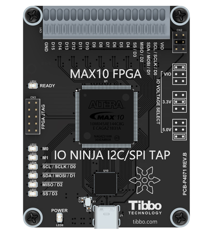
I2C/SPI Tap is an affordable sniffer that can monitor I2C and SPI communications. The Tap connects to your PC via a USB cable and is compatible with IO Ninja terminal/sniffer software.
Features
Designed for use with IO Ninja software (http://ioninja.com/).
Reliably captures
I2Ctraffic at clock speeds of up to 700KHz and SPI traffic at clock speeds of up to 24MHz [1]; all fourSPImodes are supported.Incorporates an
I2CandSPItest sequence generator for self-testing the Tap.Based on Intel MAX10 FPGA.
Has 16 buffered IO lines
D0~15connected to a quick-release terminal block.All buffers act as level shifters allowing the Tap to work with logical signals in the 1.8V-5V range.
Eight LEDs onboard:
Green Ready LED;
Two general-purpose green LEDs
M0andM1for mode indication;Four yellow LEDs for indicating the state of IO lines
D0~3(sufficient for monitoringI2andSPIcommunications);Blue Power LED.
Built-in test generator outputs fixed I2C and SPI data sequences.
High-speed (480Mbps) USB2.0 interface on a USB-C connector.
Supplied with a USB-C cable.
USB-powered, no additional external power necessary.
Compact, outside dimensions only 82 x 74 x 30 mm.
Product functionality may be expanded in the future:
Onboard FPGA is reconfigurable via the USB interface;
Sixteen IO lines provide ample room to grow;
It is envisioned that the tap’s abilities may be expanded to handle such protocols as…
Quad-SPI;SDIO;Single-wire bus;
and more!
Using the I2C/SPI Tap
Please see the documentation for the I2C/SPI Tap plugin.
Using Build-in Test Generator
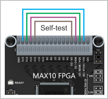
I2C and SPI firmware (FPGA configurations) for this Tap include test generators producing sustained test traffic at 400KHz and 24MHz respectively.
Test I2C signals are generated on D14 (SDA) and D15 (SCL).
Test SPI signals are generated on D12 (SS), D13 (MISO), D14 (MOSI), and S15 (SCLK).
To receive the test traffic, connect two or four wires as shown on the diagram above.
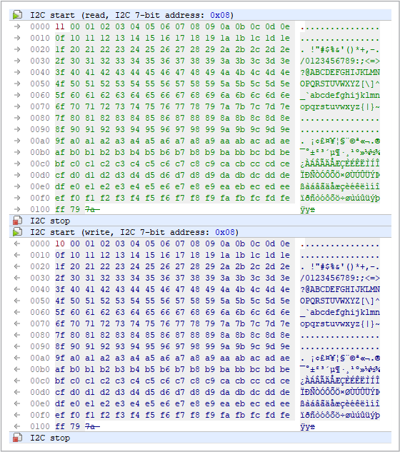
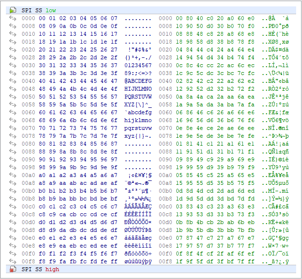
Here is the data you will receive from the test generators.
I2C Test Sequence
SPI Test Sequence
Specifications
I2C/SPI Tap is supplied with a USB cable.
Hardware Specifications [2] [3]
Parameter |
Specification |
|---|---|
USB port |
USB 2.0, high-speed (480 MHz), USB-C connector |
Supported I2C clock speeds |
Up to 700 kHz |
Supported SPI clock speeds |
Up to 24 MHz [1] |
Operating temperature |
0 to +60 degrees C |
Operating relative humidity |
10–90% |
Mechanical dimensions |
82 x 74 x 30 mm |